FireEye Agent Stopped

FireEye Agent Stopped and will not restart.

Index

Issue

Configuration File invalid when trying the upgrade/reinstall, agent stpped and will not start and

PS C:\Program Files (x86)\FireEye\xagt> .\xagt.exe –cfg-export ‘C:\Install\export.cfg’ Error: 65548

Resolution

Need to rename C:\ProgramData\FireEye\xagt

Move-Item "C:\ProgramData\FireEye\xagt" "xagt.old"

Then run (This will error with Error 1738) but it will re-create the xagt folder

& "C:\Program Files (x86)\FireEye\xagt\xagt.exe" --cfg-export 'C:\Install\Export.cfg'

Then import the config from the installation media or from an exported working configuration from another server.

& "C:\Program Files (x86)\FireEye\xagt\xagt.exe" --cfg-import 'C:\Install\GoodConfig.cfg'

OR

& "C:\Program Files (x86)\FireEye\xagt\xagt.exe" --cfg-import 'C:\Install\agent_config.json'
[Read More]

A1 WiFi Smart Control - part 1

Post Description

Index

Content

Overview

Enable control of IR devices using Home Assistant using a off-the-shelf product with minimal changes.

I have chosen Smart Universal Remote controller IR WiFi Intelligent Home Remote Suitable for Alexa Google Assistant as it was cheap £14.99, and used the TuyaSmart app which meant it’s probably based on esp8266.

This post is post 1, which will cover the product basic teardown.

Teardown

I have just received the product and it looks pretty good, i haven’t powered it up as there have ben reports of problems when using Tuya convert if you allow it to update.

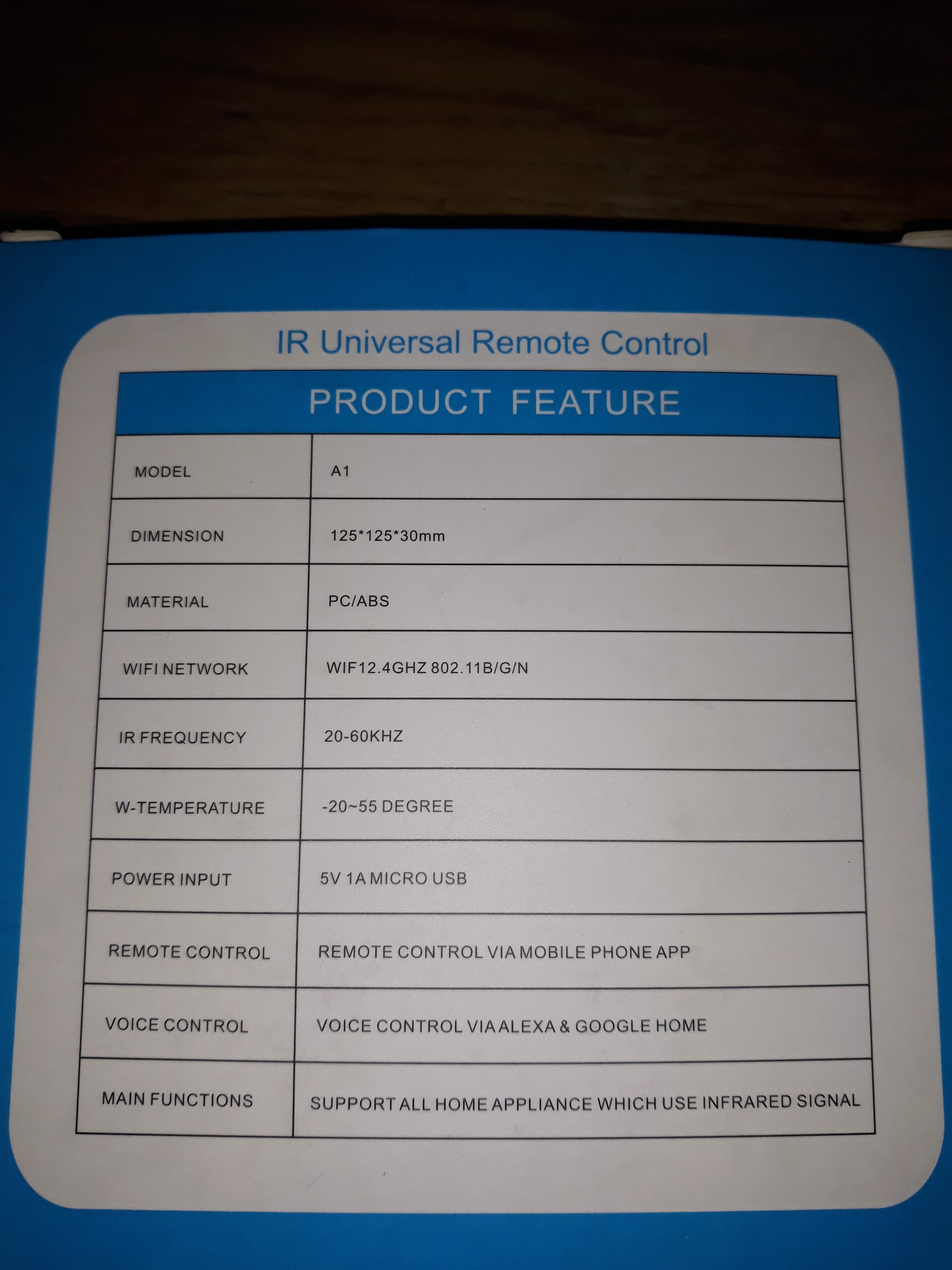
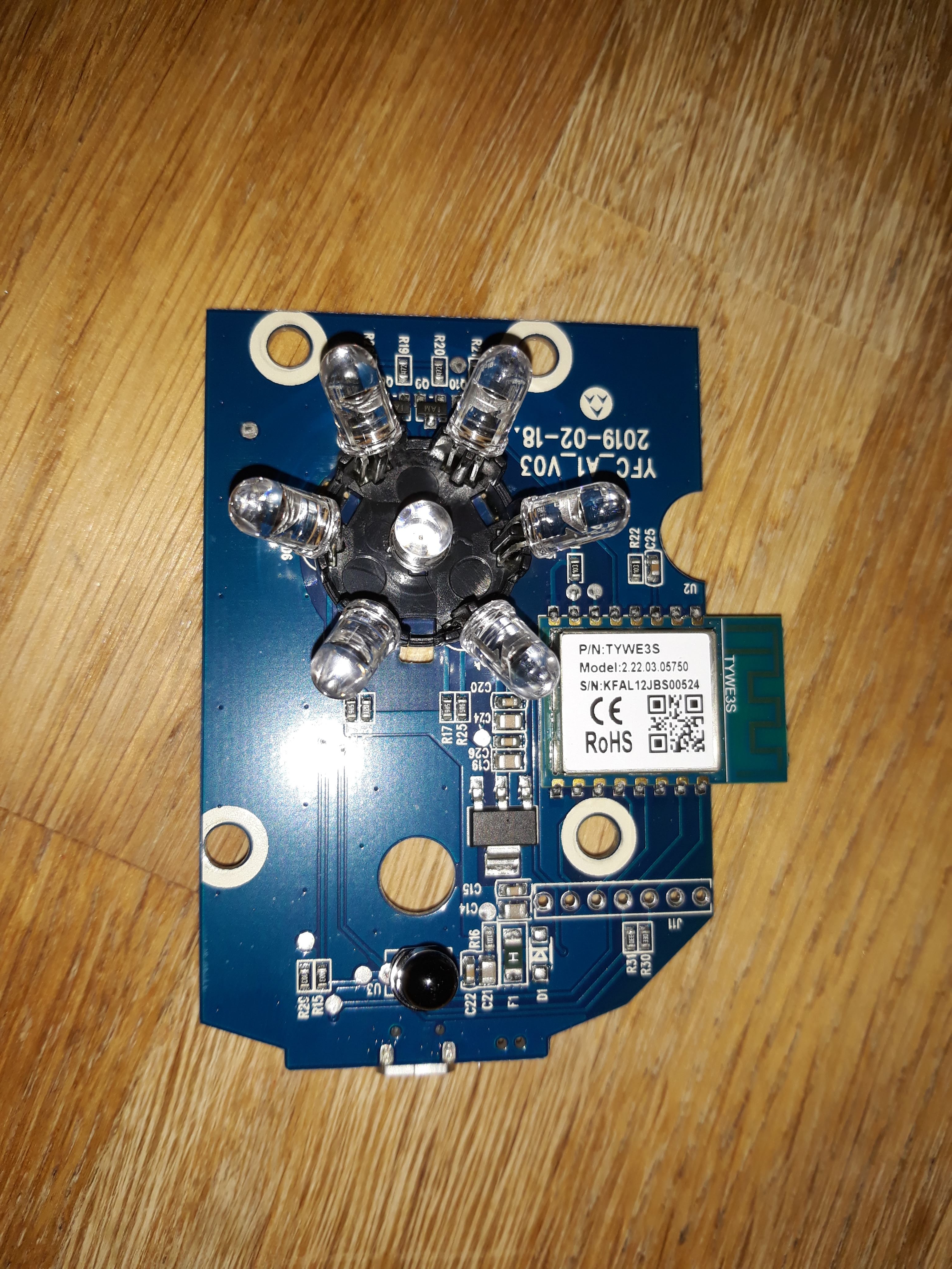
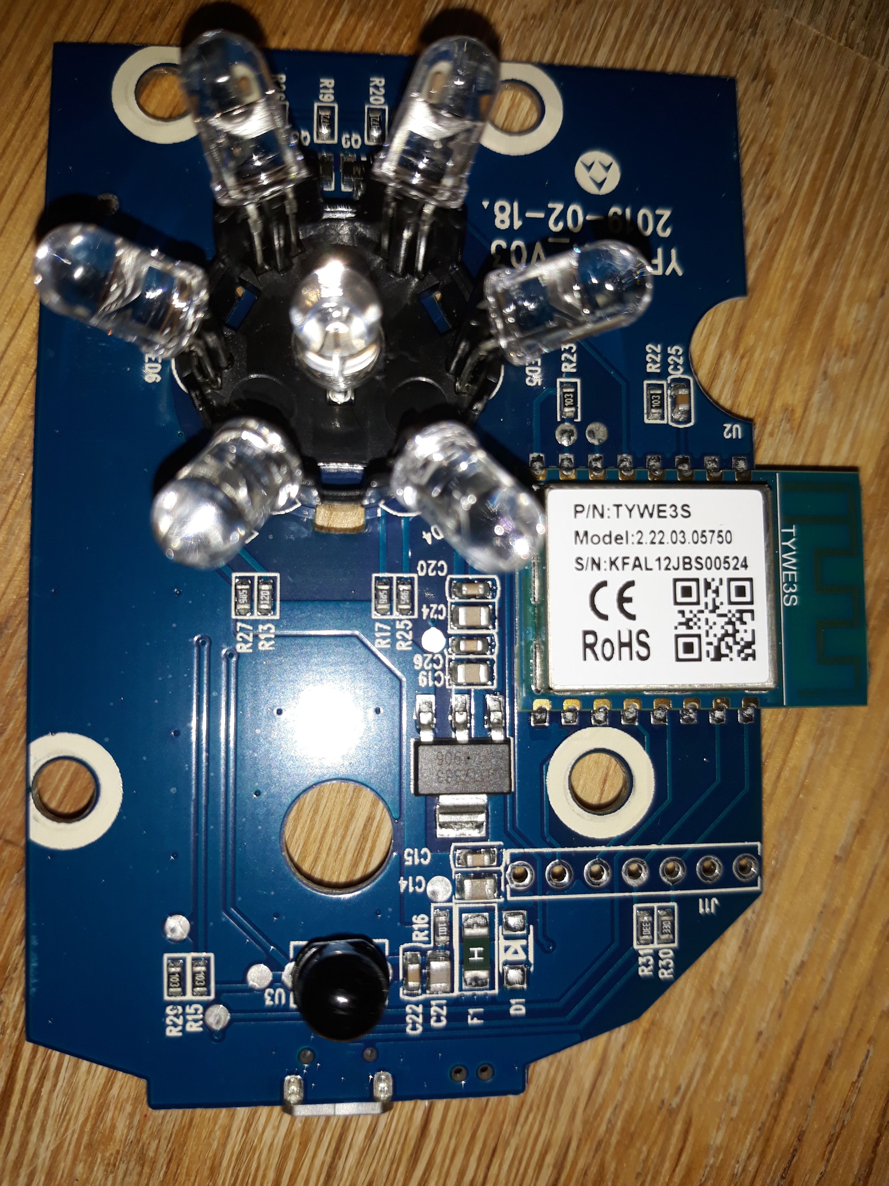
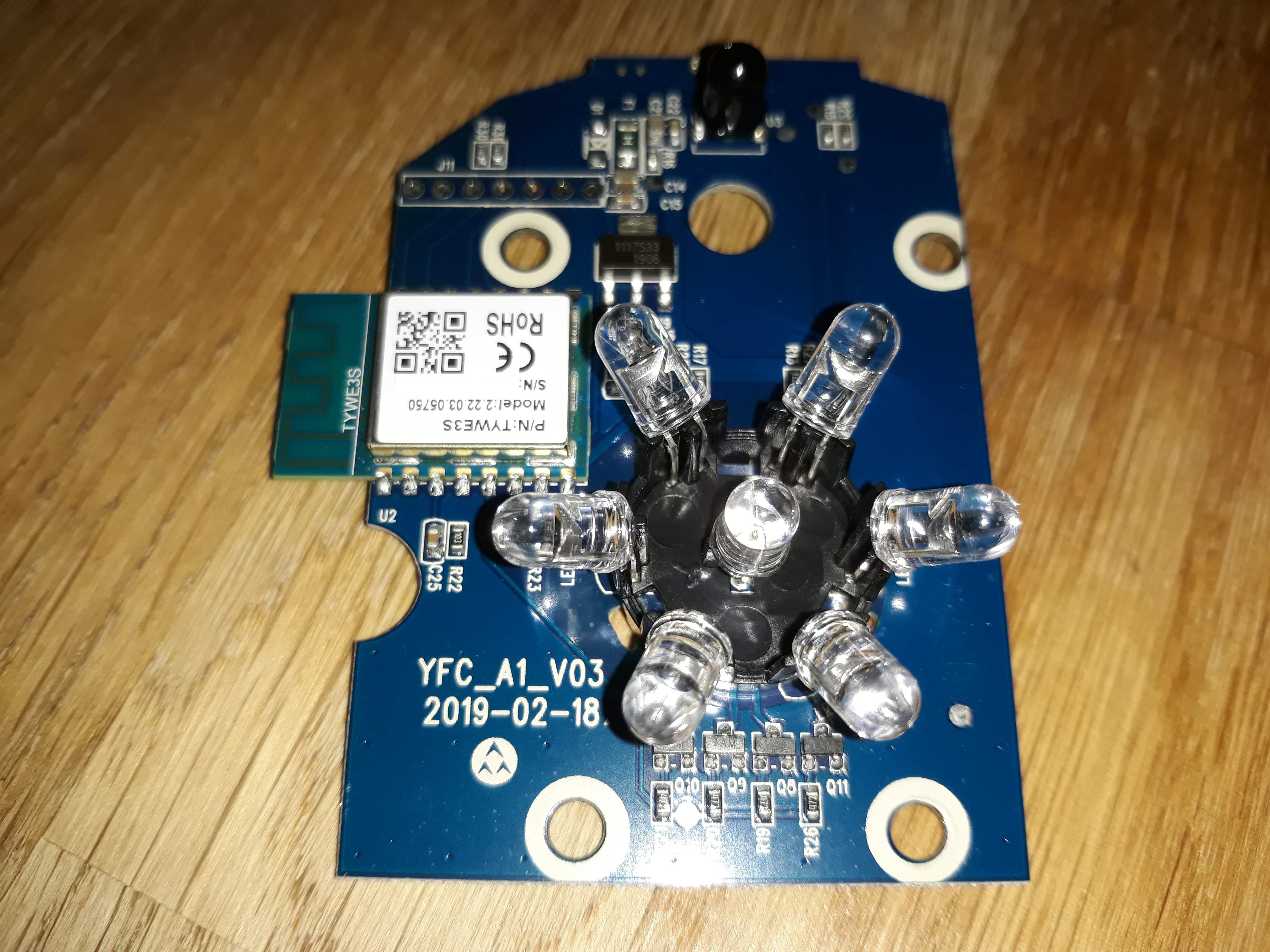
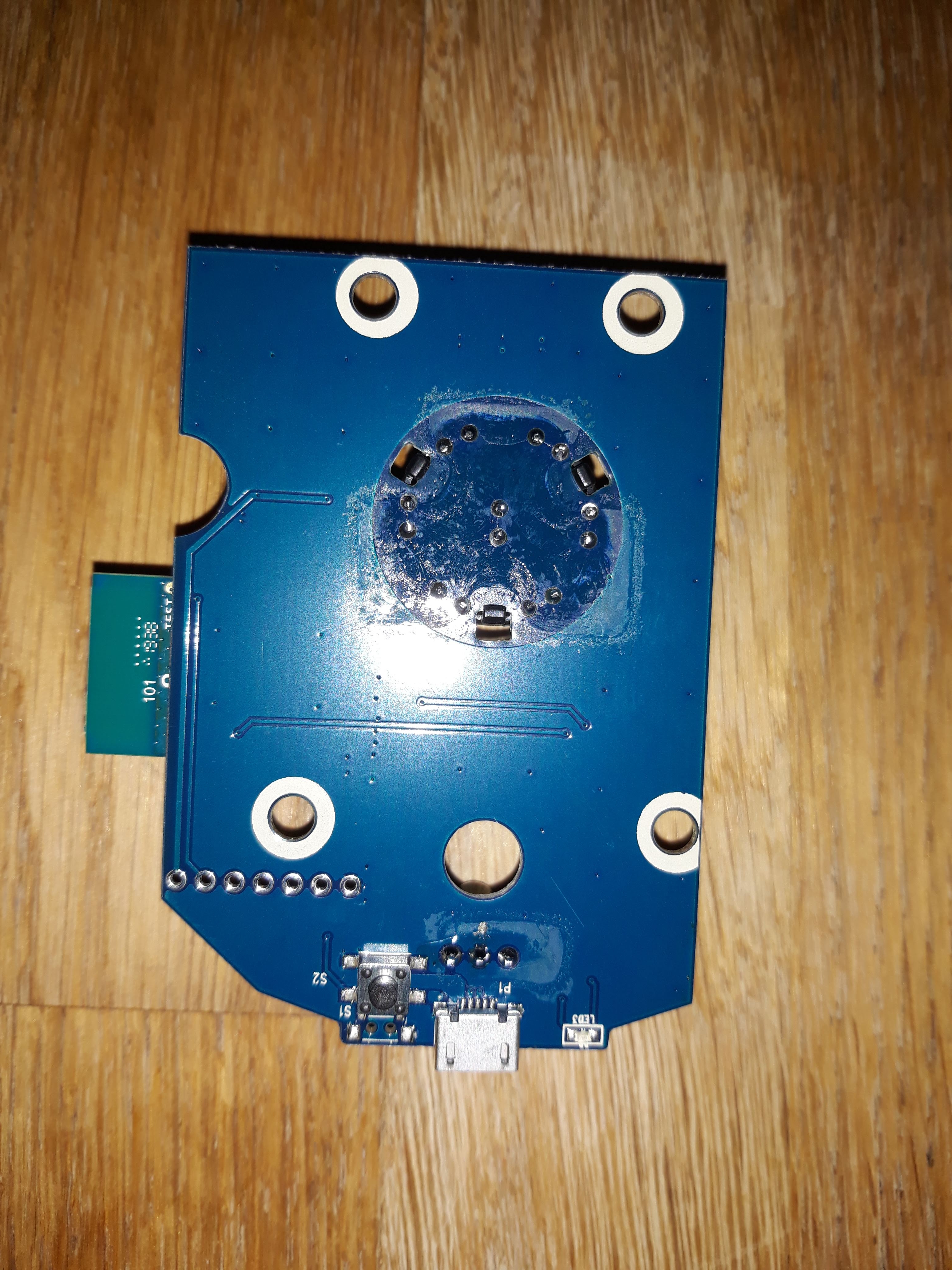
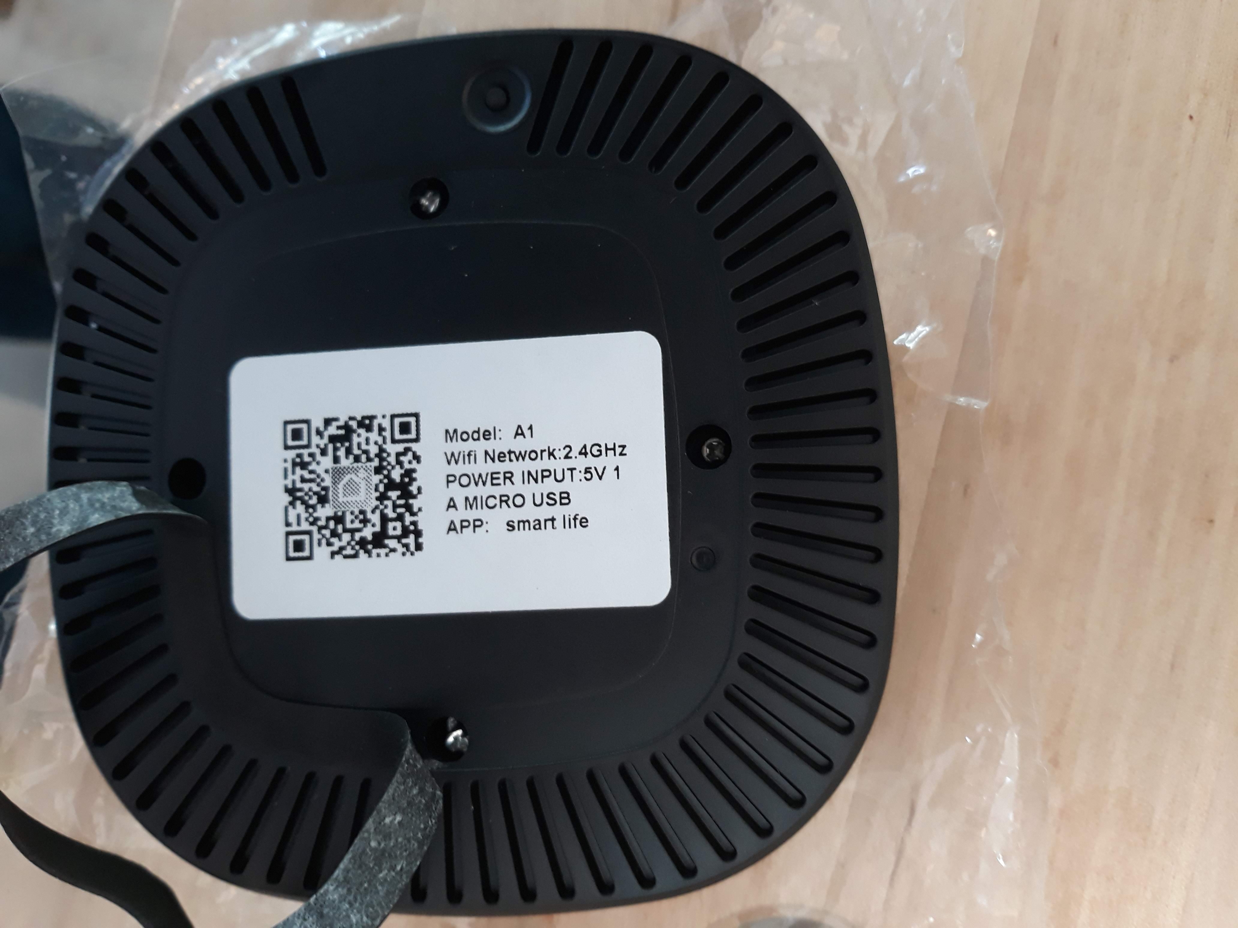
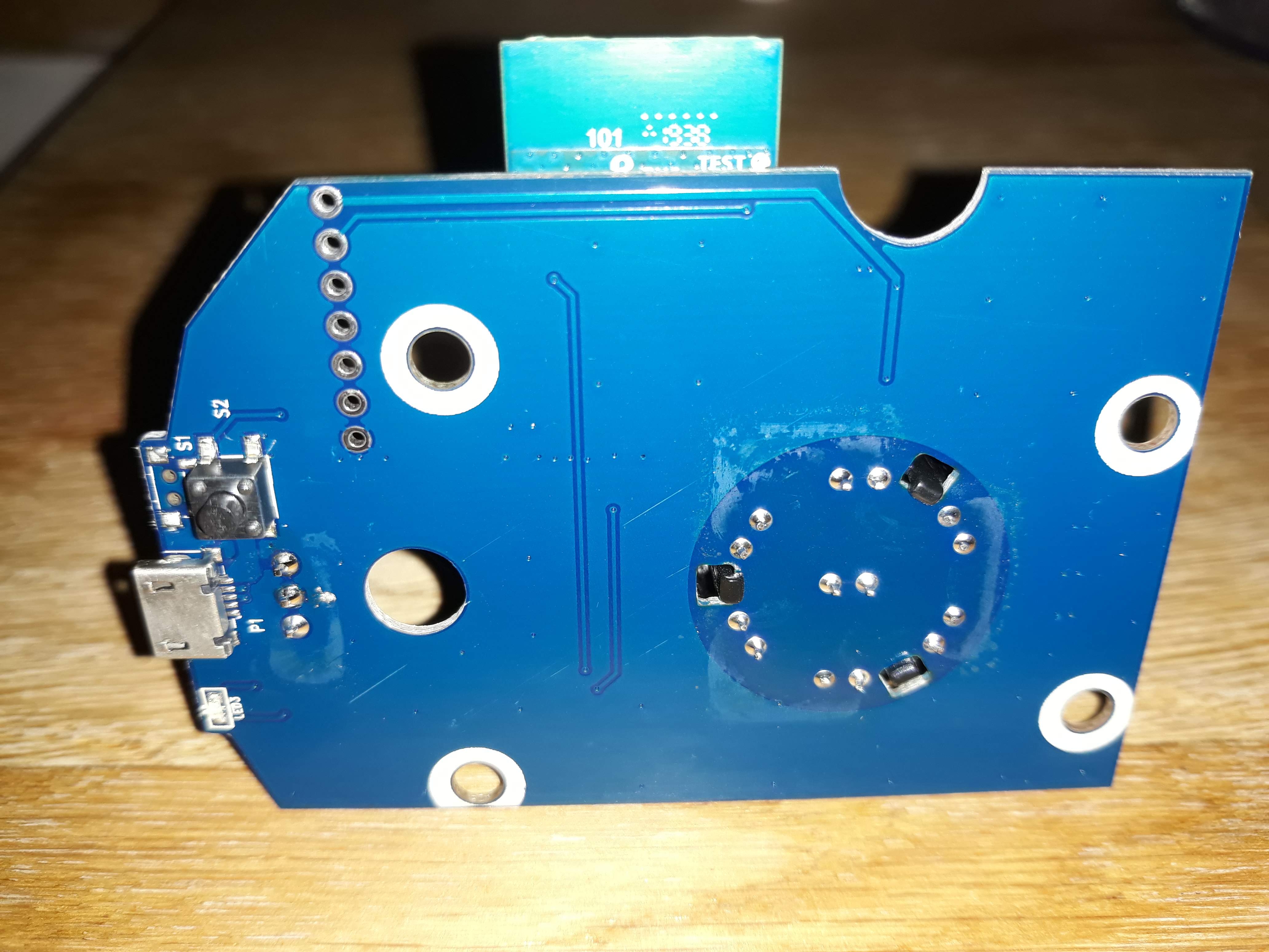
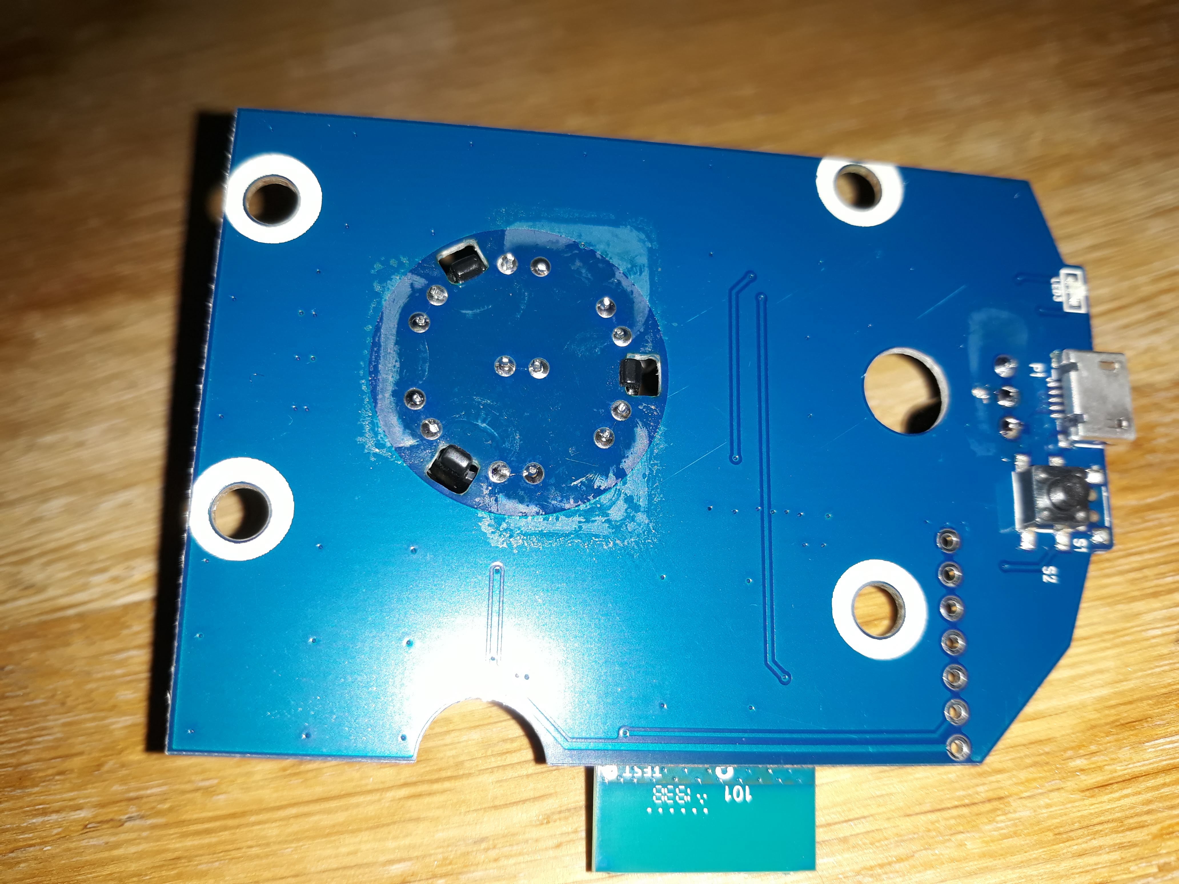
Here are photos of the unit. The unit is screwed together by 4 phillips screws under the foam padding on the bottom.

box_front box_rear inside pcb_front pcb_front_closeup_1 pcb_front_closeup_2 pcb_rear a1_back pcb_rear_closeup_1 pcb_rear_closeup_2

next steps

Work out pin out for J11, so we can program it.

[Read More]

A first look at OpenAuto

A first look at OpenAuto. This is the first post of the project.

Index

Overview

OpenAuto is an AndroidAuto(tm) headunit emulator based on aasdk library and Qt libraries. I plan to build a headunit to be a simple plug ‘n’ play but with the AndroidAuto support.

Initially I planned to build it via source this was original plan, but following a rethink I’m now using Crankshaft-NG. I have left the code build instructions the post in case I need to change this decision.

Hardware

  • Raspberry PI 3
  • USB Audio adapter with headphone output and mic input
  • HDMI display

Re-thinking the solution

Software

Upon a rethink it has occured to me that it’ll be better to use Crankshaft-NG which is a pre image based on OpenAuto.

Steps performed

  • Download Crankshaft-NG
  • Image SD card with downloaded image
  • Enable Dev_Mode
    • Edit /boot/crankshaft/chrankshaft_env.sh
      • DEV_MODE=1
      • DEV_MODE_APP=1
  • Power on pi
  • SSH to pi
    • Using pi/raspberry
  • Update
    sudo apt update
    sudo apt upgrade -y
    sudo apt dist-upgrade -y
    sudo reboot
    
  • Rename host (Optional). Update each file with the new hostname.
    sudo nano /etc/hostname
    sudo nano /etc/hosts
    
  • Enable onboard BT You must reboot after this.
    crankshaft bluetooth builtin
    sudo reboot
    
  • Set crankshaft to pariable for 120 secs
    crankshaft bluetooth pairable
    
  • Pair phone

Original Plan

Software

  • Raspbian Buster Lite
  • aasdk
  • OpenAuto

Update Raspbian

  • Login as pi
  • Set GPU memory to 256MB via raspi-config
  • Ensure Raspbian is fully updated.
    sudo apt update -y
    sudo apt upgrade -y
    sudo apt dist-upgrade -y
    sudo apt autoclean -y
    
  • add basic GUI addgui
    #sudo apt install -y --no-install-recommends xserver-xorg raspberrypi-ui-mods
    #sudo apt install -y xvfb
    sudo apt-get install --no-install-recommends xserver-xorg
    sudo apt-get install --no-install-recommends xinit
    sudo apt-get install -y lxde-core lxappearance
    sudo apt-get install -y lightdm
    
  • add default gui and autologin /etc/systemd/system/default.target → /lib/systemd/system/graphical.target

aasdk

Build

Build aasdk from the source code. This takes about 40 minutes.

  • Install pre-requirements
    sudo apt-get install -y libboost-all-dev libusb-1.0.0-dev libssl-dev cmake libprotobuf-dev protobuf-c-compiler protobuf-compiler
    
  • Get aasdk code
    cd ~/
    git clone -b development https://github.com/opencardev/aasdk.git
    
  • Prepare build environment
    mkdir aasdk_build
    cd aasdk_build
    
  • Generate cmake files
    cmake -DCMAKE_BUILD_TYPE=Release ../aasdk
    
  • Build aasdk
    make
    

OpenAuto

Build OpenAuto from source code. This takes about 40 minutes.

Build

  • Install pre-requirements
    sudo apt-get install -y libqt5multimedia5 libqt5multimedia5-plugins libqt5multimediawidgets5 qtmultimedia5-dev libqt5bluetooth5 libqt5bluetooth5-bin qtconnectivity5-dev pulseaudio librtaudio-dev librtaudio6
    
  • Build ilclient from Raspberry PI 3 firmware
    cd /opt/vc/src/hello_pi/libs/ilclient
    make
    
  • Get OpenAuto code
    cd ~/
    git clone -b crankshaft-ng https://github.com/opencardev/openauto.git
    
  • Prepare build environment
    mkdir openauto_build
    cd openauto_build
    
  • Generate cmake files
    cmake -DCMAKE_BUILD_TYPE=Release -DRPI3_BUILD=TRUE -DAASDK_INCLUDE_DIRS="/home/pi/aasdk/include" -DAASDK_LIBRARIES="/home/pi/aasdk/lib/libaasdk.so" -DAASDK_PROTO_INCLUDE_DIRS="/home/pi/aasdk_build" -DAASDK_PROTO_LIBRARIES="/home/pi/aasdk/lib/libaasdk_proto.so" ../openauto
    
  • Build OpenAuto
    make
    

OpenAuto First Run

Run OpenAuto

/home/pi/openauto/bin/autoapp
[Read More]

repost - Reading OBD2 data without ELM327 - Part2

Repost from https://m0agx.eu/2018/01/02/reading-obd2-data-without-elm327-part-2-k-line/

Index

Content

Reading OBD2 data without ELM327, part 2 – K-Line

Originally Posted on 2018-01-02 at Original Post

K-Line is another popular OBD2 interfacing standard, that has been used in European cars before CAN bus became common. There are a couple of physical variations (K-line, K+L, KKL) and slightly different protocols (KWP2000 or Keyword Protocol, and ISO 9141) running on those lines. Basically all you need to talk to an older car is an MCU with a UART and a single transistor. 🙂

This is a second post in series about OBD2. First one is here.

Physical layer

K-line is just a fancy name for a single-wire half-duplex UART running at 10400 baud and using 0/12V voltage levels. The “high” voltage level is actually the battery voltage (so it varies between 12V and 14,4V if the engine is running). Regular UARTs use 0/3,3V levels or 0/5V, while RS-232 uses +12/-12V.

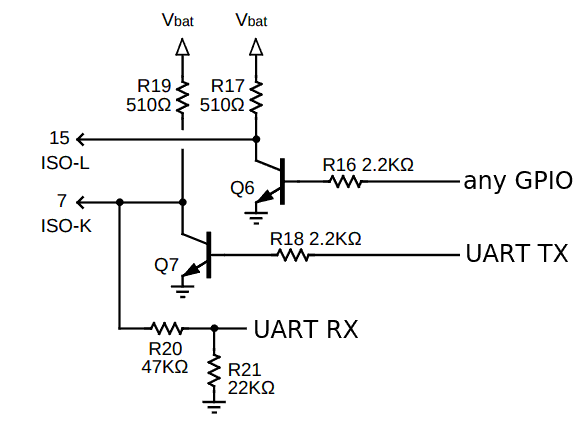
The physical interface is quite simple – basically you have to interface MCU’s RX and TX lines to the 12V line. This is a reference schematic taken straight from ELM327 Datasheet: Kline Wiring Kline Wiring

Reception from the K-Line is done with a simple voltage divider. The values may have to be slightly changed if the MCU uses 3,3V. Assuming that the K-Line voltage can vary between 12V and 14,4V the output of the divider should not exceed MCU supply voltage.

Transmission is also simple – just an NPN transistor in the open collector configuration with pullup resistor. The only catch here is that UART idle voltage is logically high, that would lead to logical low voltage on the K-Line because of the transistor. The solution is to enable TX inversion in UART peripheral. Not all MCUs support that. For example Kinetis E and XMEGA can invert the TX pin, while older AVRs (like ATmega328p) can not. Of course you could use a PNP transistor or another way to externally invert the TX logic level.

The L-Line is transmit only from the MCU side. It is used to transmit a 5-baud wakeup sequence (alongside K-line) in one of the older protocols. Only older cars have the L-line present.

Protocols

I gathered the data by capturing signals with a logic analyzer between a no-name ELM327 USB cable and Freematics OBD emulator. All communication takes place at 10400 baud (8N1), except the initial pulses or slow initialization. Every protocol data frame ends with a checksum. The checksum is a simple 8-bit sum of all bytes, initial value is 0. It is transmitted as the last byte.

KWP2000 – fast initialization

Fast initialization begins with a 25ms low and 25ms high state of the K-Line (and maybe doing the same with the L-Line, I did not dig into the official specs, it certainly does not hurt 🙂 ). Then a frame of 0xC1 0x33 0xF1 0x81 0x66 is transmitted by the UART to the car. The car responds with 0x83 0xF1 0x11 0xC1 0x8F 0xEF 0xC4 (sum of all received bytes except the last should be 0xC4). If the car responds with a valid frame (ie. valid CRC) it can be assumed that initialization succeeded (the response may depend on the car/year, but as far as basic OBD2 is concerned – anything valid means a good initialization).

If the procedure fails (the car does not respond with a valid frame), then the slow initialization procedure should be attempted after at least ~2,5 seconds!

Slow initialization

For slow initialization it is best to switch the TX line to GPIO, because the UART may not be able to work at 5 baud, so software-controlled delays are more appropriate. The sequence starts with a 200ms low, 400ms high/low/high/low, 227ms high. This may also be done with the L-Line (at the same time).

The car will respond with 3 bytes, for example: 0x55 0xEF 0x8F. Depending on the values the protocol will be either KWP2000 or ISO-9141. First byte is always 0x55. The other bytes are respectively called KB1 and KB2.

If KB1 and KB2 are both 0x08 0x08 or 0x94 0x94, then the protocol to be used is ISO-9141, otherwise it is KWP2000.

After receiving the first frame from the car, an inverted KB2 has to be sent to the car. In this example (inverted 0x8F) it is 0x70. The car will then respond (single byte) with its inverted ECU address that will be used for all future requests.

Requesting a PID – KWP2000

The request frame is: 0xC2 0xF1 .

Some examples (PID values in bold, ELM request 010C means sending exactly those characters + newline via serial terminal to an OBD2 USB cable):

  • ELM request 010C (mode 01, PID 0x0C – RPM)
    • request:
      C2 33 F1 01 0C F3 (0x33 is the ECU address, 0x01 mode, 0x0C PID, 0xF3 checksum)
    • response:
      84 F1 11 41 0C 1F 40 32 (1F40 = 2000rpm, see formula)
    • response:
      84 F1 11 41 0C 1F 44 36 (1F44 = 2001rpm, see formula)
  • ELM request 010D (mode 01, PID 0x0D – speed km/h)
    • request:
      C2 33 F1 01 0D F4
    • response:
      83 F1 11 41 0D 64 37 (0x64 = 100km/h)
    • response:
      83 F1 11 41 0D 38 0B (0x38 = 56km/h)
  • ELM request 0100 (mode 01, PID 0x00 – available mode 01 PIDs)
    • request:
      C2 33 F1 01 00 E7
    • response:
      86 F1 11 41 00 FF FF FF FF C5 (0xFFFFFFFF = all pids)
  • ELM request 0902 (mode 09, PID 0x02 – get VIN, this * * request is special as response comes in several frames, the result is ASCII, left padded with zeros)
    • request:
      C2 33 F1 09 02 F1
    • response:
      87 F1 11 49 02 01 00 00 00 31 06
      87 F1 11 49 02 02 41 31 4A 43 D5
      87 F1 11 49 02 03 35 34 34 34 A8
      87 F1 11 49 02 04 52 37 32 35 C8
  • keepalive – I’ve seen this being sent by the ELM327 every 2 seconds (if no other requests were sent), but I think that requesting mode 01 PID 0x00 could also be a good keepalive.
    • request:
      C1 33 F1 3E 23
    • response:
      81 F1 11 7E 01

Note that the first response byte contains frame length. It is encoded on the 6 lower bits. The length does not include the initial length byte, 2 type bytes and checksum byte (so you would have to add 4 to the number to get the whole frame length in bytes).

Requesting a PID – ISO-9141

This is an older protocol. Main issue is that the response length is not transmitted, so you have to either have a lookup table of all possible lengths (ie. PID+length pairs) or receive byte-by-byte, compute the checksum on the fly and process when the checksum is valid (plus some timeout logic).

Examples (PID values in bold):

  • ELM request 010C (mode 01, PID 0x0C – RPM)
    • request:
      68 6A F1 01 0C D0
    • response:
      48 6B 11 41 0C 1F 40 70
  • ELM request 0100 (mode 01, PID 0x00 – available mode 01 PIDs)
    • request:
      68 6A F1 01 00 C4
    • response:
      48 6B 11 41 00 FF FF FF FF 01
  • ELM request 010D (mode 01, PID 0x0D – speed km/h)
    • request: 68 6A F1 01 0D D1
    • reponse: 48 6B 11 41 0D 00 12
  • ELM request 0902 (mode 09, PID 0x02 – get VIN, this request is special as response comes in several frames, the result is ASCII, left padded with zeros)
    • request:
      68 6A F1 09 02 CE
    • response:
      48 6B 11 49 02 01 00 00 00 31 41
      48 6B 11 49 02 02 41 31 4A 43 10
      48 6B 11 49 02 03 35 34 34 34 E3
      48 6B 11 49 02 04 52 37 32 35 03
      48 6B 11 49 02 05 32 33 36 37 E6
[Read More]

Repost - Reading OBD2 data without ELM327 - Part1

Repost from https://m0agx.eu/2017/12/27/reading-obd2-data-without-elm327-part-1-can/

Index

Content

Reading OBD2 data without ELM327, part 1 – CAN

Originally Posted on 2017-12-27 at Original Post

All modern cars have an OBD2 diagnostic connector that allows reading many engine and drivetrain parameters like RPM, vehicle speed, temperatures etc.

Most of car interfaces use a special protocol translating chip like ELM327 or STN1110 to convert different vehicle protocols (that depend on the age and brand of the car) into an easier to use serial protocol with AT-commands.

I wanted to build a datalogger that would fit into a OBD2 connector. There was no space to fit my microcontroller and another chip to do protocol conversion, so I investigated and reverse-engineered the most common OBD2 protocols to be able to implement them directly on my MCU.

This is the first post in series about OBD2. Second one is here.

Basics

Because the OBD2 standards are not freely available I decided to buy an OBD2 emulator from Freematics, connect it to a chinese OBD2 USB cable and sniff the traffic with a protocol analyzer. Later I have found out that the emulator prints out all traffic to the terminal, so the analyzer was not necessary.

There are several physical layer (think “the wires”) standards (CAN, K-Line, VPV, PWM) and several protocols that run over those wires. This post is about one of them – the CAN bus used for OBD2 (formally standarized as ISO 15765-4).

CAN bus

CAN bus standard allows many devices to send and receive messages over a single (twisted) pair of wires. Each message has a message identifier (11 or 29 bit long), length field and up to 8 payload bytes (+some other flags that are not needed for OBD2). There is no notion of sender or receiver. The message ID is used to distinguish the source (or destination).

Devices connected to a CAN bus must have a CAN transceiver (can be thought of similar to an RS-485 driver) and a CAN controller. The transceiver is always a separate chip. The controller may be integrated into a microcontroller or be a separate chip.

OBD2 modes and PIDs

OBD2 defines several modes (which can for example deliver live data, freeze frame data, diagnostic trouble codes etc.). Each of the modes support many PIDs (Parameter IDs). For example mode 01 PID 0x0C is current engine RPM. A PID can have up to 4 bytes and requires a formula to convert those bytes to a meaningful reading. Wikipedia has an excellent list of PIDs. Not all PIDs are available on every car.

OBD2 and CAN

The CAN-flavor of OBD2 comes in 4 variants:

  • 500kbps with standard (11 bit) identifiers
  • 250kbps with standard (11 bit) identifiers
  • 500kbps with extended (29 bit) identifiers
  • 250kbps with extended (29 bit) identifiers

It is hard to predict which one is used by the car. I have chosen to simply request mode 01 PID 0x00 (that is always available) using different variants.

Requesting a PID

The message is always 8 bytes long, even if less information is required. The first byte specifies the length within payload (in this case the first byte is 2 because only the mode and PID bytes are used).

PID message request (bytes):

0x02 <mode> <pid> 0x00 0x00 0x00 0x00 0x00

For example to request mode 0x01 PID 0x0C (RPM) simply send:

0x02 0x01 0x0C 0x00 0x00 0x00 0x00 0x00

Message ID must be 0x7DF for standard (11 bit) addressing and 0x18DB33F1 for extended (29 bit) addressing. Each message will be acknowledged by the car.

PID response

The response will carry a message ID of 0x7E8 (standard addressing) or 0x18DAF111 (extended), so the CAN controller receive filter must pass those message IDs. Example:

0x04 0x41 0x0C 0x31 0x64 0x00 0x00 0x00

First byte is the length of the payload field (in this case 4 bytes are valid), second byte – it is a response to mode 0x01 PID, third byte is the PID (0x0C), bytes 0x31 and 0x64 are byes A and B of the PID.

To get RPM you have to use a formula from table of PIDs PID Table. In this case the engine speed is (256 * 0x31 + 0x64)/4 = 3161 rpm.

Summary

Everything you need to get live OBD2 data from your car is to send a simple CAN frame and wait for the response. You don’t need a protocol translator like ELM327 or STN1110 (though they will support more protocols and vehicle types, including all communication quirks found through the years).

I have described only getting data for mode 01 (mode 02 is identical). Other modes may require different data formats. For example getting the VIN number (due to its length) is more complicated, because it has to be split between many CAN frames.

Example driver code

This is a piece of code from my upcoming OBD2 datalogger project. It runs on a Kinetis MKE06Z128 and uses the built-in CAN controller. The driver requires FreeRTOS and some other files, but still it provides an easy reference on implementing OBD2 communications with MSCAN peripheral.

#include <FreeRTOS/include/FreeRTOS.h>
#include <FreeRTOS/include/task.h>
#include "misc.h"
#include <MKE06Z4.h>
#include "obd_can.h"
#include <string.h>

#define DEBUG_ID DEBUG_ID_OBD_CAN
#include <debug.h>

#if DEFAULT_BUS_CLOCK == 20000000
//Values were calculated using the spreadsheet in dev_documentation directory
#define CANBTR0_500KBAUD 0xC3
#define CANBTR1_500KBAUD 0x34
#define CANBTR0_250KBAUD 0xC7
#define CANBTR1_250KBAUD 0x34
#else
#error "CAN baud registers not defined for this bus clock!"
#endif

#define CAN_PID_RESPONSE_TIMEOUT_ms 50
//ISO 15765-4 identifiers, reverse engineered from ELM327 communication ;)
#define CAN_OBD2_STD_ID_ECU_REQ_ID 0x7DF
#define CAN_OBD2_STD_ID_ECU_RESPONSE_ID 0x7E8
#define CAN_OBD2_STD_ID_ECU_RESPONSE_FILTER_MASK 0x7FF //simply all 11 bits must match
#define CAN_OBD2_EXT_ID_ECU_REQ_ID 0x18DB33F1
#define CAN_OBD2_EXT_ID_ECU_RESPONSE_ID 0x18DAF111
#define CAN_OBD2_EXT_ID_ECU_RESPONSE_FILTER_MASK 0x1FEFFFFF //simply all 29 bits must match *except* the RSRR

typedef struct {
	uint32_t identifier;
	bool identifier_is_extended;
	uint8_t length;
	uint8_t payload[8];
	uint8_t padding1[2];
} can_rx_frame_t;

static TaskHandle_t _local_task_handle = NULL;
static volatile can_rx_frame_t _rx_frame;
static bool _use_extended_id;
static uint32_t _obd_id_request;
static uint32_t _obd_id_response;

static void obd_can_transmit(uint32_t identifier, bool identifier_is_extended,
		const uint8_t *payload, uint8_t payload_length);
static void obd_can_tx_abort(void);

void obd_can_init(can_speed_t speed, bool use_extended_id){
	_local_task_handle = xTaskGetCurrentTaskHandle();

	portENTER_CRITICAL();
	SIM->SCGC |= SIM_SCGC_MSCAN_MASK;

	SIM->PINSEL1 |= SIM_PINSEL1_MSCANPS_MASK; //CAN_TX PTE7, CAN_RX PTH2

	portEXIT_CRITICAL();

	MSCAN->CANCTL0 |= MSCAN_CANCTL0_INITRQ_MASK; //enter controller initialization mode
	while (!(MSCAN->CANCTL1 & MSCAN_CANCTL1_INITAK_MASK)) {
		//wait for the controller to enter initialization mode
		vTaskDelay(2);
	}

	MSCAN->CANCTL1 = MSCAN_CANCTL1_CLKSRC_MASK /*use bus clock*/
			| MSCAN_CANCTL1_CANE_MASK; //enable CAN module*/

	//	MSCAN->CANCTL1 |= MSCAN_CANCTL1_LOOPB_MASK; //enable loopback for testing

	//set baud
	if (speed == can_speed_500kbaud){
		MSCAN->CANBTR0 = CANBTR0_500KBAUD;
		MSCAN->CANBTR1 = CANBTR1_500KBAUD;
		debugf("500k baud init");
	} else {
		MSCAN->CANBTR0 = CANBTR0_250KBAUD;
		MSCAN->CANBTR1 = CANBTR1_250KBAUD;
		debugf("250k baud init");
	}

	_use_extended_id = use_extended_id;
	if (_use_extended_id){
		debugf("Using extended 29-bit IDs");
		_obd_id_request = CAN_OBD2_EXT_ID_ECU_REQ_ID;
		_obd_id_response = CAN_OBD2_EXT_ID_ECU_RESPONSE_ID;
	} else {
		debugf("Using standard 11-bit IDs");
		_obd_id_request = CAN_OBD2_STD_ID_ECU_REQ_ID;
		_obd_id_response = CAN_OBD2_STD_ID_ECU_RESPONSE_ID;
	}

	MSCAN->CANRIER = MSCAN_CANRIER_RXFIE_MASK; //enable RX interrupt

	//RX filter - standard ID
	MSCAN->CANIDAR_BANK_1[0] = (uint8_t) (CAN_OBD2_STD_ID_ECU_RESPONSE_ID >> 3); //this register holds bits 10-3 of the ID
	MSCAN->CANIDAR_BANK_1[1] = (CAN_OBD2_STD_ID_ECU_RESPONSE_ID & 0x7) << MSCAN_TSIDR1_TSID2_TSID0_SHIFT;
	//MSCAN->CANIDAR_BANK_1[2] and [3] - don't care
	MSCAN->CANIDMR_BANK_1[0] = (uint8_t) ~((CAN_OBD2_STD_ID_ECU_RESPONSE_FILTER_MASK >> 3));
	MSCAN->CANIDMR_BANK_1[1] = (uint8_t) ~((CAN_OBD2_STD_ID_ECU_RESPONSE_FILTER_MASK & 0x7) << MSCAN_TSIDR1_TSID2_TSID0_SHIFT);
	MSCAN->CANIDMR_BANK_1[2] = 0xFF;
	MSCAN->CANIDMR_BANK_1[3] = 0xFF;

	debugf("%02X%02X %02X%02X%02X%02X",
			MSCAN->CANIDAR_BANK_1[0],
			MSCAN->CANIDAR_BANK_1[1],
			MSCAN->CANIDMR_BANK_1[0],
			MSCAN->CANIDMR_BANK_1[1],
			MSCAN->CANIDMR_BANK_1[2],
			MSCAN->CANIDMR_BANK_1[3]
	);

	MSCAN->CANIDAR_BANK_2[0] = CAN_OBD2_EXT_ID_ECU_RESPONSE_ID >> 21;
	MSCAN->CANIDAR_BANK_2[1] = ((CAN_OBD2_EXT_ID_ECU_RESPONSE_ID >> (20/*source bit position*/- 7/*destination bit position*/))
			& MSCAN_TEIDR1_TEID20_TEID18_MASK)
			| ((CAN_OBD2_EXT_ID_ECU_RESPONSE_ID >> (17 - 2)) & MSCAN_TEIDR1_TEID17_TEID15_MASK)
			| MSCAN_TEIDR1_TEIDE_MASK;
	MSCAN->CANIDAR_BANK_2[2] = (uint8_t) (CAN_OBD2_EXT_ID_ECU_RESPONSE_ID >> 7);
	MSCAN->CANIDAR_BANK_2[3] = (uint8_t) (CAN_OBD2_EXT_ID_ECU_RESPONSE_ID << 1);

	MSCAN->CANIDMR_BANK_2[0] = (uint8_t) ~(CAN_OBD2_EXT_ID_ECU_RESPONSE_FILTER_MASK >> 24);
	MSCAN->CANIDMR_BANK_2[1] = (uint8_t) ~(CAN_OBD2_EXT_ID_ECU_RESPONSE_FILTER_MASK >> 16);
	MSCAN->CANIDMR_BANK_2[2] = (uint8_t) ~(CAN_OBD2_EXT_ID_ECU_RESPONSE_FILTER_MASK >> 8);
	MSCAN->CANIDMR_BANK_2[3] = (uint8_t) ~(CAN_OBD2_EXT_ID_ECU_RESPONSE_FILTER_MASK);

	debugf("%02X%02X%02X%02X %02X%02X%02X%02X",
			MSCAN->CANIDAR_BANK_2[0],
			MSCAN->CANIDAR_BANK_2[1],
			MSCAN->CANIDAR_BANK_2[2],
			MSCAN->CANIDAR_BANK_2[3],
			MSCAN->CANIDMR_BANK_2[0],
			MSCAN->CANIDMR_BANK_2[1],
			MSCAN->CANIDMR_BANK_2[2],
			MSCAN->CANIDMR_BANK_2[3]
	);

	MSCAN->CANIDAC = MSCAN_CANIDAC_IDAM(0); //use two 32-bit acceptance filters

	NVIC_SetPriority(MSCAN_RX_IRQn, 5);
	NVIC_EnableIRQ(MSCAN_RX_IRQn);

	MSCAN->CANCTL0 &= ~MSCAN_CANCTL0_INITRQ_MASK; //exit initialization mode

	while (MSCAN->CANCTL1 & MSCAN_CANCTL1_INITAK_MASK) {
		//wait for the controller to exit initialization mode
		vTaskDelay(2);
	}

	MSCAN->CANRIER = MSCAN_CANRIER_RXFIE_MASK; //enable RX interrupt

	debugf("OBD CAN initialized");
}

void obd_can_deinit(void){
	NVIC_DisableIRQ(MSCAN_RX_IRQn);

	MSCAN->CANCTL0 |= MSCAN_CANCTL0_INITRQ_MASK; //enter controller initialization mode

	while (!(MSCAN->CANCTL1 & MSCAN_CANCTL1_INITAK_MASK)) {
			//wait for the controller to enter initialization mode
	}

	MSCAN->CANCTL1 = 0; //disable CAN module

	SIM->SCGC &= ~SIM_SCGC_MSCAN_MASK; //disable clock to module
}

void obd_can_task(void){
	//no need for keepalive messages
}

static void obd_can_tx_abort(void) {
	uint8_t busy_buffers = (~MSCAN->CANTFLG) & MSCAN_CANTFLG_TXE_MASK; //zero means a busy buffer
	MSCAN->CANTARQ = busy_buffers;          //writing one triggers abort request
	while (MSCAN->CANTAAK != busy_buffers) {
		vTaskDelay(2); //wait for abort ack
	}
}

static void obd_can_transmit(uint32_t identifier, bool identifier_is_extended,
		const uint8_t *payload, uint8_t payload_length) {

	uint8_t empty_buffer_mask = MSCAN->CANTFLG & MSCAN_CANTFLG_TXE_MASK;
	if (!empty_buffer_mask) { //this should never happen as only one buffer is used in a lockstep
		debugf("TX busy, dropping frame"); //and after a timeout all transmissions are aborted
		return;
	}

	//select transmit buffer
	MSCAN->CANTBSEL = MSCAN_CANTBSEL_TX(empty_buffer_mask);
	debugf("Buffers available %02X selected %02X, payload length %d", empty_buffer_mask, MSCAN->CANTBSEL, payload_length);

	MSCAN->TBPR = 0; //priority of this buffer

	if (identifier_is_extended) {
		MSCAN->TEIDR0 = identifier >> 21;
		MSCAN->TEIDR1 = ((identifier >> (20/*source bit position*/- 7/*destination bit position*/))
				& MSCAN_TEIDR1_TEID20_TEID18_MASK)
								| ((identifier >> (17 - 2)) & MSCAN_TEIDR1_TEID17_TEID15_MASK)
								| MSCAN_TEIDR1_TEIDE_MASK;
		MSCAN->TEIDR2 = identifier >> 7;
		MSCAN->TEIDR3 = identifier << 1;
	} else {
		MSCAN->TSIDR0 = (uint8_t) (identifier >> 3); //this register holds bits 10-3 of the ID
		MSCAN->TSIDR1 = (identifier & 0x7) << MSCAN_TSIDR1_TSID2_TSID0_SHIFT;
	}

	for (uint8_t i = 0; i < 8; i++){
		MSCAN->TEDSR[i] = payload[i];
	}
	MSCAN->TDLR = payload_length;

	//enable transmission of this buffer
	uint8_t transmit_flag = MSCAN->CANTBSEL & MSCAN_CANTBSEL_TX_MASK;
	debugf("transmit flag = %02X", transmit_flag);

	MSCAN->CANTFLG = transmit_flag;
}

int32_t obd_can_get_pid(pid_mode_t mode, uint8_t pid, obd_pid_response_t *target_response) {
	uint8_t data[8];
	data[0] = 2; //"real" length of the payload, CAN frame has to be 8 bytes long
	data[1] = mode;
	data[2] = pid;
	data[3] = 0x0;
	data[4] = 0x0;
	data[5] = 0x0;
	data[6] = 0x0;
	data[7] = 0x0;

	obd_can_transmit(_obd_id_request, _use_extended_id, data, sizeof(data));
	//data is transmitted - now wait for other the response or timeout
	uint32_t status = ulTaskNotifyTake(
			pdTRUE/*clear notification value when ready*/,
			pdMS_TO_TICKS(CAN_PID_RESPONSE_TIMEOUT_ms));
	if (status) {
		debugf("rx frame id=%X id_ext=%d length=%d", (unsigned int)_rx_frame.identifier,
				_rx_frame.identifier_is_extended, _rx_frame.length);

		for (uint32_t i = 0; i < _rx_frame.length; i++) {
			debugf("rx payload[%ld]=%02X", i, _rx_frame.payload[i]);
		}

		//not all PIDs return 4 bytes but higher layer will handle it
		target_response->byte_a = _rx_frame.payload[3];
		target_response->byte_b = _rx_frame.payload[4];
		target_response->byte_c = _rx_frame.payload[5];
		target_response->byte_d = _rx_frame.payload[6];

		return _rx_frame.payload[0] - 2; //length of the particular PID response (minus PID and mode bytes)
	} else { //timeout
		debugf("timeout");
		obd_can_tx_abort();
		return OBD_PID_ERR;
	}
}

extern void MSCAN_RX_IRQHandler(void);
void MSCAN_RX_IRQHandler(void) {
	if (MSCAN->REIDR1 & MSCAN_REIDR1_REIDE_MASK) { //frame has extended identifier
		_rx_frame.identifier_is_extended = true;
		//getting the ID back together is a nightmare, see MSCAN reference manual...
		_rx_frame.identifier = MSCAN->REIDR0 << 21;
		_rx_frame.identifier |=
				(MSCAN->REIDR1 & MSCAN_REIDR1_REID20_REID18_MASK) << (18 - 5);
		_rx_frame.identifier |=
				(MSCAN->REIDR1 & MSCAN_REIDR1_REID17_REID15_MASK) << 15;
		_rx_frame.identifier |= MSCAN->REIDR2 << 7;
		_rx_frame.identifier |= (MSCAN->REIDR3 & MSCAN_REIDR3_REID6_REID0_MASK) >> 1;
	} else {
		_rx_frame.identifier_is_extended = false;
		_rx_frame.identifier = ((MSCAN->RSIDR1 & MSCAN_RSIDR1_RSID2_RSID0_MASK)
				>> MSCAN_RSIDR1_RSID2_RSID0_SHIFT) | (MSCAN->RSIDR0 << 3);
	}

	if (unlikely(_rx_frame.identifier != _obd_id_response)){
		MSCAN->CANRFLG = MSCAN_CANRFLG_RXF_MASK; //clear RX interrupt flag
		return; //drop frames that are not OBD2 replies
	}

	_rx_frame.length = MSCAN->RDLR & MSCAN_RDLR_RDLC_MASK;

	for (uint32_t i = 0; i < _rx_frame.length; i++) {
		_rx_frame.payload[i] = MSCAN->REDSR[i];
	}

	MSCAN->CANRFLG = MSCAN_CANRFLG_RXF_MASK; //clear RX interrupt flag

	BaseType_t xHigherPriorityTaskWoken = pdFALSE;
	xTaskNotifyFromISR(_local_task_handle, pdTRUE, eSetValueWithOverwrite,
			&xHigherPriorityTaskWoken);
	portYIELD_FROM_ISR(xHigherPriorityTaskWoken);
}
[Read More]

A Good Module

DRAFT - Not complete - in progress

Background

Over the last few years I’ve build a module pipeline using Plaster, Invoke-Build, PSDepend, PSScriptAnalyzer, Pester and Jenkins.

Recently I’ve been slowly pulling out various parts of the module in to separate repos as I found I was updating several modules with the sames files when I changed the base module.

I know I can just re-plaster the template over the top but I was looking for a solution to make this a automated step as part of the pipeline.

This post will detail the Generic Test Suite part of the plaster template.

A ‘Good’ Module

I’ve defined a good module as:

  • Code Coverage > 60%
  • Has at least 1 public function
  • Must pass PSScriptAnalyzer
  • Each public function must have help
  • Each public function must have an example
  • Every parameter must exist in help
  • Every file must be UTF-8

Plaster Template Overview

Plaster is a template-based file and project generator written in PowerShell.

For more details see Plaster

Plaster Template details

The plaster template was written to create a standard module structure, it has grown over several years and it still growing.

Each module is built using a Plaster template.

Each Module pulls a repository that contains a set of tests to ensure that the module has all the basic requirements for a good module.

PlasterTemplateRepo

Generic Test Suite

I have defined this ‘Generic Test Suite’ in a set of Pester tests which are run before any other test in the pipeline.

The ‘Generic Test Suite’ is not included in each module but are pulled from the repository each time it is build, this enabled me to fix tests and add new ones without having to update every module.

The downfall to this approach is that I may add a test that causes some modules to fail on the next build.

I have decided that this is the expected outcome as I will only be using the Generic Test Suite for tests that are required to meet the Good Module requirements as detailed above.

Tests

Here is the GenericTestSuiteRepo for all the generic tests.

These tests check the following:

  • File Encoding is UTF-8
  • Public Functions have Help
  • Module Manifest is valid
  • Exports are correct
  • Files are Signed

PSDepend

This is a simple PowerShell dependency handler. You might loosely compare it to bundle install in the Ruby world or pip install -r requirements.txt in the Python world.

PSDepend allows you to write simple requirements.psd1 files that describe what dependencies you need, which you can invoke with Invoke-PSDepend

For more details see PSDepend

Invoke-Build

Invoke-Build is a build and test automation tool. For more details see Invoke-Build

Invoke-Build Tasks

Jenkins Pipeline

For more details see Jenkins

Stages

Clean

This stage prepares the environment. It uses PSDepend to install requirements to the artifact folder in the repo.

Analyse

This stage runs PSScriptAnalyzer

BuildPS1M

This Stage builds the separated ps1 files into a single PSM1

Test

This Stage first runs the Generic test suite then it will run the tests for the module functions.

Archive

This stage archives the build artifact and test results to Jenkins

Publish

This Stage publishes the PowerShell module to the nuget repository.

VScode

I’ve added vscode tasks to assist with local development. Each Pipeline Stage is mapped to a VScode task.

This to run the tests locally all I need to do is ctrl+p and type:

task test

Tasks

[Read More]

Moved from wordpress

This will be just a quick first test post.

I am using github pages for this and using Jekyll so I can use Markdown to author my posts. It actually is a lot easier than I thought it was going to be.

I’m in the process of moving the old content to this blog, so please report any issues with the old content via the issue tracker.

[Read More]
Tags: old blog

Symantec Endpoint Protection - Sweet32

To resolve Nessus vulnerabilities below

42873 SSL Medium Strength Cipher Suites Supported

94437 SSL 64-bit Block Size Cipher Suites Supported (SWEET32)

Edit the following files

"C:\Program Files (x86)\Symantec\Symantec Endpoint Protection Manager\apache\conf\ssl\ssl.conf"

"C:\Program Files (x86)\Symantec\Symantec Endpoint Protection Manager\apache\conf\ssl\sslForClients.conf"

From:

SSLCipherSuite HIGH:!MEDIUM:!LOW:!aNULL:!eNULL:3DES:!RC4

To:

SSLCipherSuite  HIGH:!aNULL:!MD5:!3DES:!CAMELLIA:!AES128

Edit

"C:\Program Files (x86)\Symantec\Symantec Endpoint Protection Manager\tomcat\conf\server.xml"

Edit SSLCipherSuite to

HIGH:!aNULL:!MD5:!3DES:!CAMELLIA:!AES128

[Read More]

Spiceworks - SWEET32

To resolve Nessus Vulnerabilities

42873 SSL Medium Strength Cipher Suites Supported

94437 SSL 64-bit Block Size Cipher Suites Supported (SWEET32)

Edit “C:\Program Files (x86)\Spiceworks\httpd\conf\httpd.conf”

Replace

SSLCipherSuite ECDHE-RSA-AES128-GCM-SHA256:ECDHE-ECDSA-AES128-GCM-SHA256:ECDHE-RSA-AES256-GCM-SHA384:ECDHE-ECDSA-AES256-GCM-SHA384:DHE-RSA-AES128-GCM-SHA256:DHE-DSS-AES128-GCM-SHA256:kEDH+AESGCM:ECDHE-RSA-AES128-SHA256:ECDHE-ECDSA-AES128-SHA256:ECDHE-RSA-AES128-SHA:ECDHE-ECDSA-AES128-SHA:ECDHE-RSA-AES256-SHA384:ECDHE-ECDSA-AES256-SHA384:ECDHE-RSA-AES256-SHA:ECDHE-ECDSA-AES256-SHA:DHE-RSA-AES128-SHA256:DHE-RSA-AES128-SHA:DHE-DSS-AES128-SHA256:DHE-RSA-AES256-SHA256:DHE-DSS-AES256-SHA:DHE-RSA-AES256-SHA:AES128-GCM-SHA256:AES256-GCM-SHA384:AES128-SHA256:AES256-SHA256:AES128-SHA:AES256-SHA:AES:CAMELLIA:DES-CBC3-SHA:!aNULL:!eNULL:!EXPORT:!DES:!RC4:!MD5:!PSK:!aECDH:!EDH-DSS-DES-CBC3-SHA:!EDH-RSA-DES-CBC3-SHA:!KRB5-DES-CBC3-SHA

With

SSLCipherSuite HIGH:!aNULL:!MD5:!3DES

[Read More]

Gitlab Nessus Vulnerabilities - Sweet32, CRIME

To resolve Nessus Vulnerabilities

20007 SSL Version 2 and 3 Protocol Detection

42873 SSL Medium Strength Cipher Suites Supported

62565 Transport Layer Security (TLS) Protocol CRIME Vulnerability

94437 SSL 64-bit Block Size Cipher Suites Supported (SWEET32)

nano /etc/gitlab/gitlab.rb

Edit the file to show the below

nginx['ssl_ciphers']="HIGH:!aNULL:!MD5:!3DES"

nginx['ssl_prefer_server_ciphers'] = "on"

Then run reconfig

sudo gitlab-ctl reconfigure

[Read More]

SQL Fails to start after SSL cert install

I came into this issue when i was resolving Nessus Vulnerability.

SSL Self-Signed Certificate (57582)

I generated a proper cert using the webserver templatye for my internal CA and used the FQDN as the Subject. Imported the cert and applied it via SQL configuration manager, then restarted SQL. Sometimes it started but failed to accept connections, other is wouldn't start.

Windows could not start the SQL Server (%sqlserverninstancename%) on Local Computer. For more information, review the System Event Log. If this is a non-Microsoft service, contact the service vendor, and refer to service-specific error code - 2146885628

  1. First we need to find the name of the service account used by the instance of SQL Server. It will probably be something like ‘SQLServerMSSQLUser$[Computer_Name]$[Instance_Name]‘.
  1. One way to do this is to navigate to the installation directory or your SQL Instance. By default SQL Server is installed at C:\Program Files\Microsoft SQL Server\MSSQL10_50.InstanceName.
  2. Right click on the MSSQL folder and click Properties.
  1. Click the Security tab and write down the user in the Group or user names window that matches the pattern of ‘SQLServerMSSQLUser$[Computer_Name]$[Instance_Name]‘.
  2. Now, open the Microsoft Management Console (MMC) by click Start -> Run, entering mmc and pressing Enter.
  3. Add the Certificates snap-in by clicking File -> Add/Remove Snap-in… and double clicking the Certificates item (Note: Select computer account and Local computer in the two pages on the wizard that appears.
  4. Click Ok.
  1. Expand Certificates (Local Computer) -> Personal -> Certificates and find the SSL certificate you imported.
  1. Right click on the imported certificate (the one you selected in the SQL Server Configuration Manager) and click All Tasks -> Manage Private Keys…
  1. Click the Add… button under the Group or user names list box.
  1. Enter the SQL service account name that you copied in step 4 and click OK.
  1. By default the service account will be given both Full control and Read permissions but it only needs to be able to Read the private key. Uncheck the Allow Full Control option.
  2. Click OK.
  3. Close the MMC and restart the SQL service.
[Read More]

Imperva DB monitoring

Imperva Db monitor cannot decrypt data

The below is required as Imperva cannot decrypt ECDH or DH Algorithms

 The below is to be run on the SQL server

Powershell to disable DH, ECDH

# Disable Diffie-Hellman and ECDH

md "HKLM:\SYSTEM\CurrentControlSet\Control\SecurityProviders\SCHANNEL\KeyExchangeAlgorithms\ECDH"

Set-ItemProperty -Path "HKLM:SYSTEM\CurrentControlSet\Control\SecurityProviders\SCHANNEL\KeyExchangeAlgorithms\ECDH" -Name Enabled -Value 0 -Force

md "HKLM:\SYSTEM\CurrentControlSet\Control\SecurityProviders\SCHANNEL\KeyExchangeAlgorithms\Diffie-Hellman"

Set-ItemProperty -Path "HKLM:SYSTEM\CurrentControlSet\Control\SecurityProviders\SCHANNEL\KeyExchangeAlgorithms\Diffie-Hellman" -Name Enabled -Value 0


# Cipher Suite Order, this may be overridden by group policy

Set-ItemProperty -Path "HKLM:\SOFTWARE\Policies\Microsoft\Cryptography\Configuration\SSL\00010002" -Name "Functions" -value "TLS_RSA_WITH_AES_256_GCM_SHA384,TLS_RSA_WITH_AES_128_GCM_SHA256,TLS_RSA_WITH_AES_256_CBC_SHA256,TLS_RSA_WITH_AES_256_CBC_SHA,TLS_RSA_WITH_AES_128_CBC_SHA256,TLS_RSA_WITH_AES_128_CBC_SHA,TLS_RSA_WITH_3DES_EDE_CBC_SHA"
[Read More]

Fix Splunk Nessus SSL Vulnerabilities

To Resolve the following Nessus Vulernabilites

20007 SSL Version 2 and 3 Protocol Detection

42873 SSL Medium Strength Cipher Suites Supported

62565 Transport Layer Security (TLS) Protocol CRIME Vulnerability

94437 SSL 64-bit Block Size Cipher Suites Supported (SWEET32)

Add the following to "C:\Program Files\SplunkUniversalForwarder\etc\system\local\server.conf"

[sslConfig]

allowSslCompression = false

useClientSSLCompression = false

sslVersions = tls1.1, tls1.2

sslVersionsForClient = tls1.1, tls1.2

cipherSuite = HIGH:!aNULL:!MD5:!3DES:!CAMELLIA:!AES128

Add the following to "C:\Program Files\SplunkUniversalForwarder\etc\system\local\inputs.conf"

[SSL]

cipherSuite = HIGH:!aNULL:!MD5:!3DES:!CAMELLIA:!AES128

allowSslCompression = false

useClientSSLCompression = false

Restart SplunkUniversalForwarder service

[Read More]

Windows 2012 - RDP password change even when NLA is enabled

If NLA is enabled on 2012 and your password expires you will be unable to login

To be able to reset your password add the following to default.rdp in your user profile\documents folder

Sometimes you try to open a remote desktop connection to a machine only to get an error message that "the password has expired".

rdperror

Add the following setting to your .rdp file ("C:\Users\<User>\Documents\Default.rdp" if you aren't using a specific one).

enablecredsspsupport:i:0

Then run mstsc and connect you'll be able to change the password

[Read More]

SSRS Subscription Auth Error

I recently moved some SSRS subscriptions between domains, there is a oneway trust between them, however when publishing a report to the desination domain using a user in the source domain the subscription errors with the following.

library!WindowsService_0!182c!12/23/2015-10:34:13:: e ERROR: Throwing Microsoft.ReportingServices.Diagnostics.Utilities.ServerConfigurationErrorException: AuthzInitializeContextFromSid: Win32 error: 5; possible reason - service account doesn’t have rights to check domain user SIDs., Microsoft.ReportingServices.Diagnostics.Utilities.ServerConfigurationErrorException: The report server has encountered a configuration error. ;

This is happens because SSRS needs to verify the subscription owner’s access to the report prior to generating and sending it. This error occurrs when you choose Windows  File Share or Send e-Mail option. As the source domain didn’t trust the destination domain that it why this failed.

However a fix bit of SQL to fix up the Subscription owner was all that was needed.

The SQL below will set the owner to be “NT Authority\System” to all subscriptions

Use ReportServer Go Declare @System as varchar (200) Select @System=(Select UserId from Users where UserName= 'NT AUTHORITY\SYSTEM') --Select * from dbo.Subscriptions where OwnerID <> @System Update dbo.Subscriptions set OwnerID=@System where OwnerID <> @System

I hope this can help others :)


[Read More]